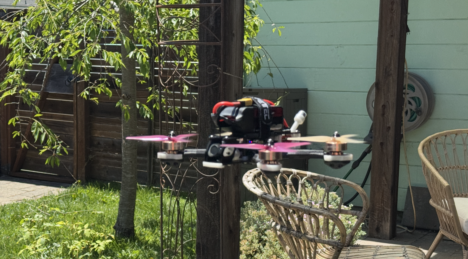
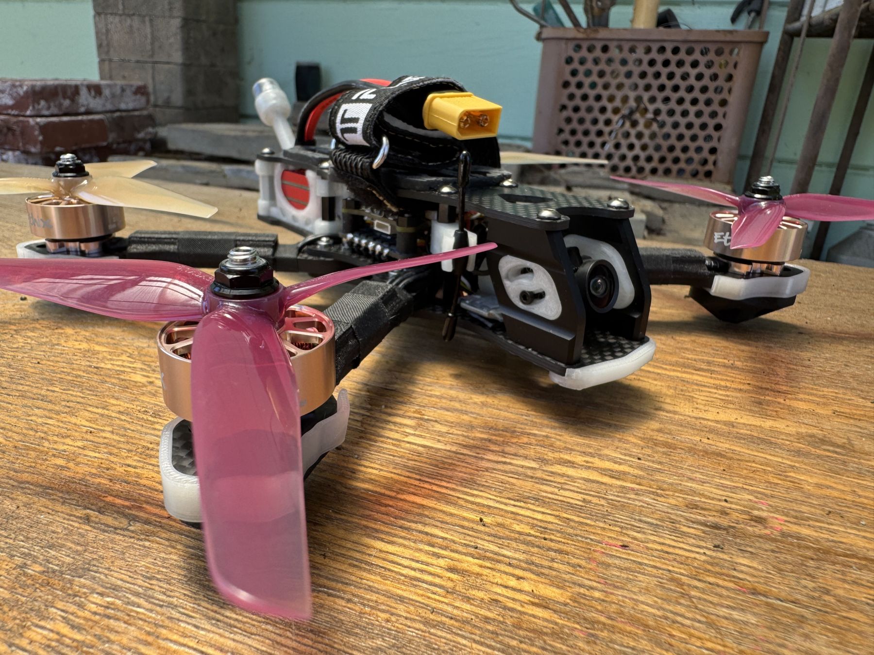
Apie šį buildą
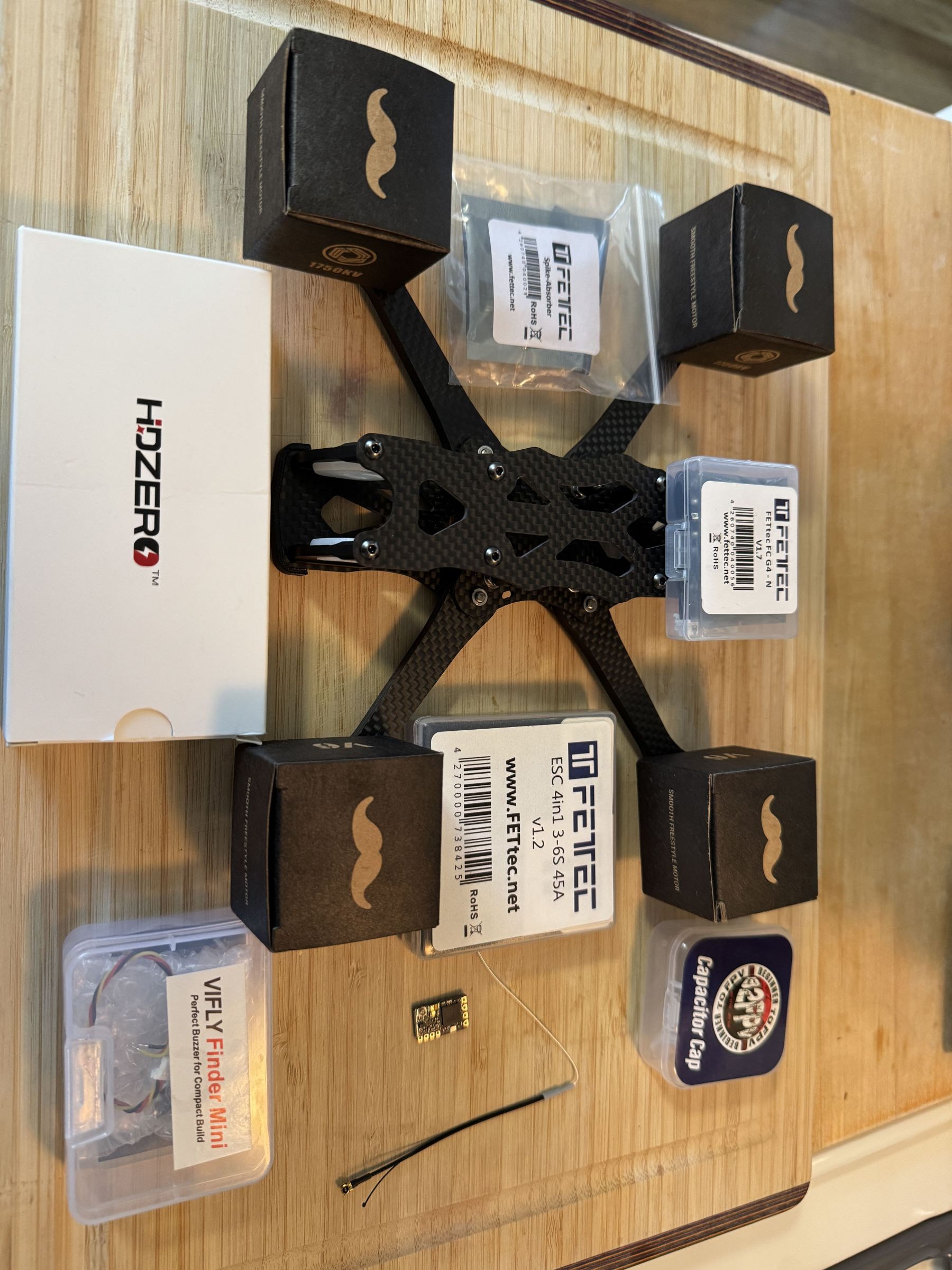
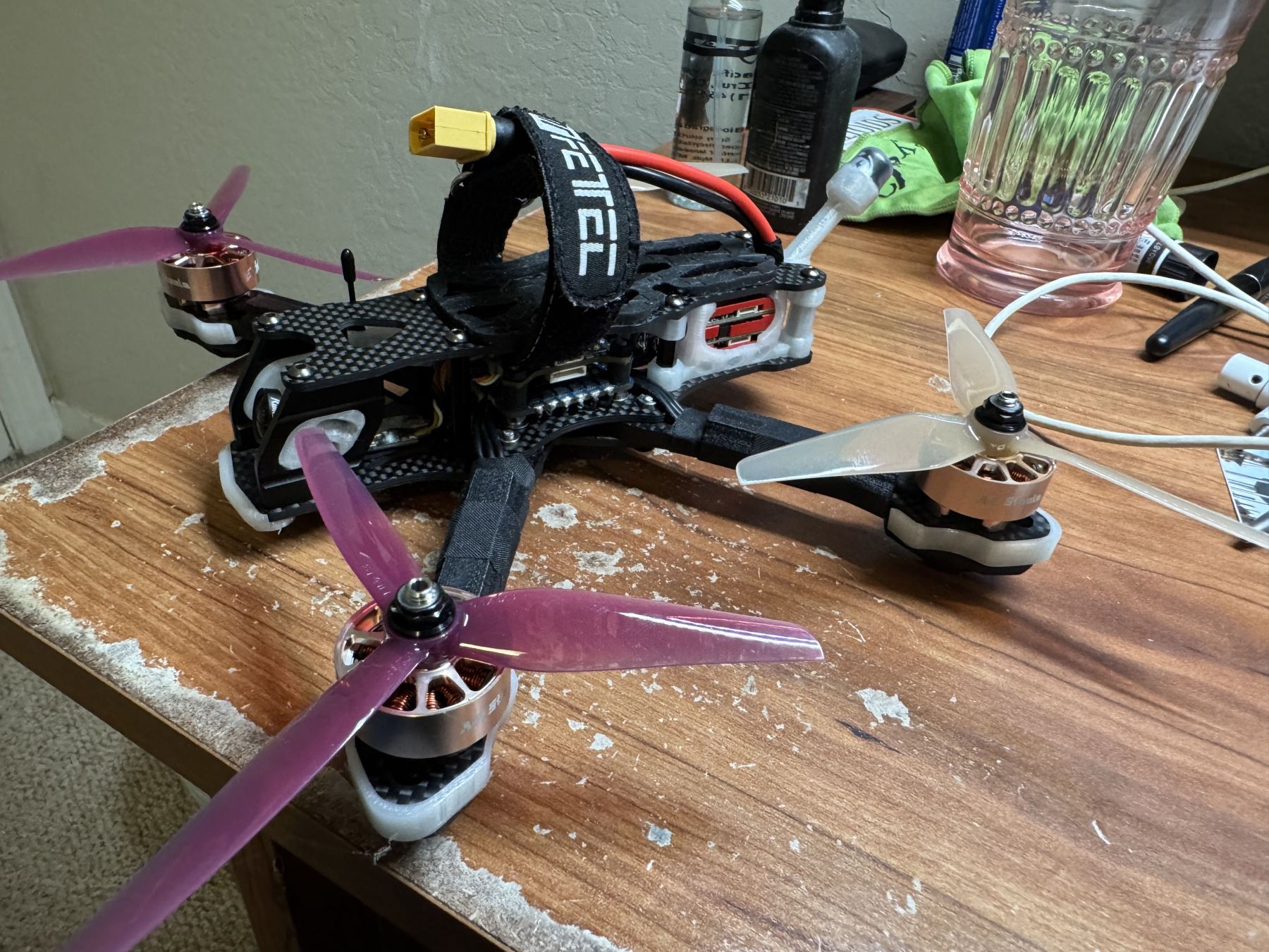
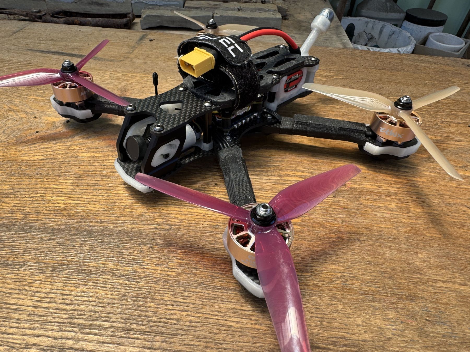
I wanted to do a kind of Apex Evo reference build based on the Evo and FETtec electronics. This frame and these electronics have a long history of working well together, and I thought Id see what all the fuss was about.
Some Factors
- FETtec ESC is fragile. You need a Spike Absorber and some chonky 50 V caps.
- ImpulseRC went out of business. I have a few new kits, so I made a full 3D model of the frame. I wish I could open-source it. Email your friends at Impulse and ask if theyll let me (I dont know them).
- Some parts are difficult to source.
- Carbon is easy to cut because I have a CNC VMC :P
- Original plan was to use legacy KISS firmware, but research showed the digital OSD was buggy. I would need to use Alpha firmware See ya, DShot -- hello 2SM+OneWire!
Criteria
- Needs to use HDZero Freestyle V2.
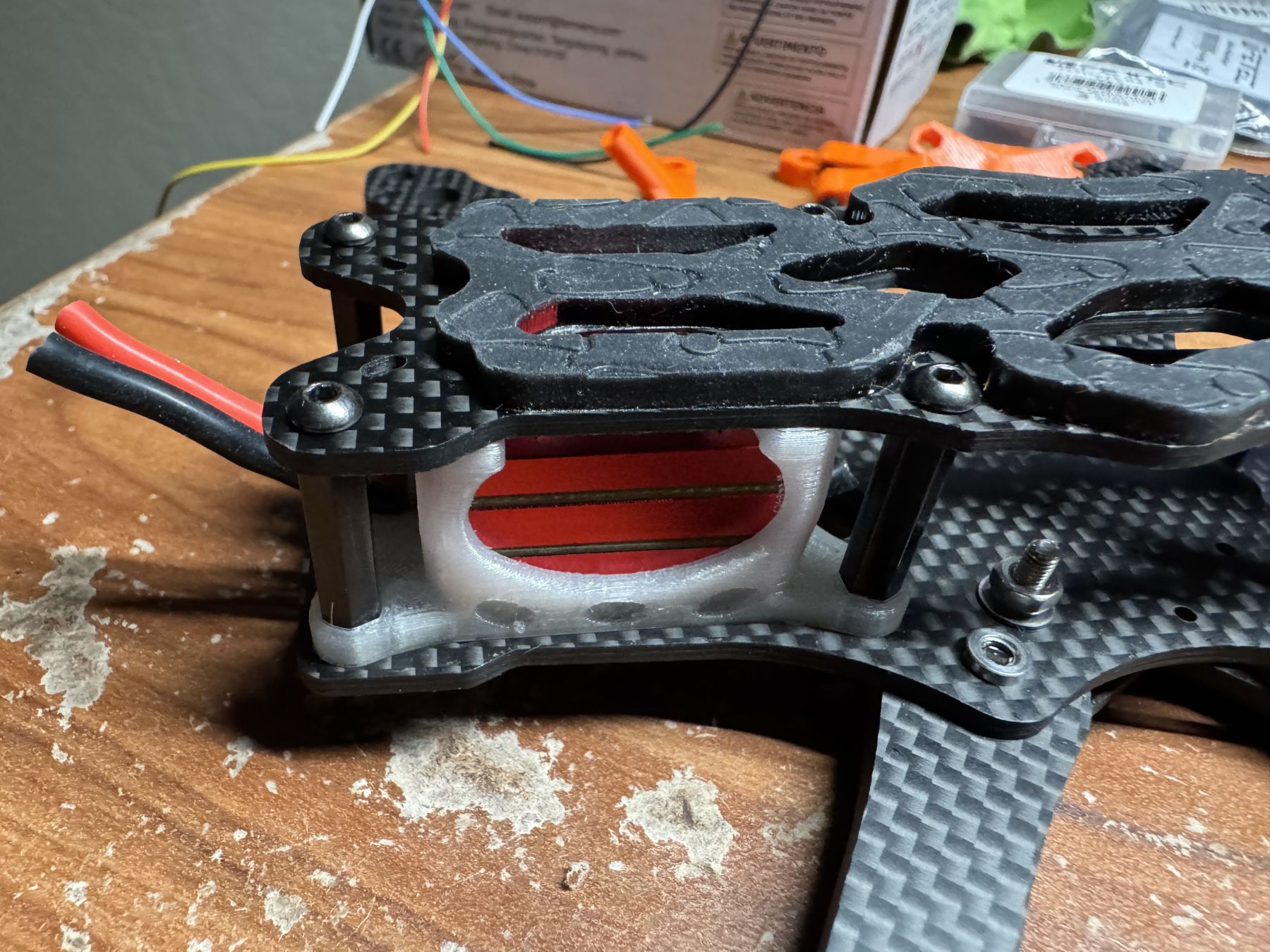
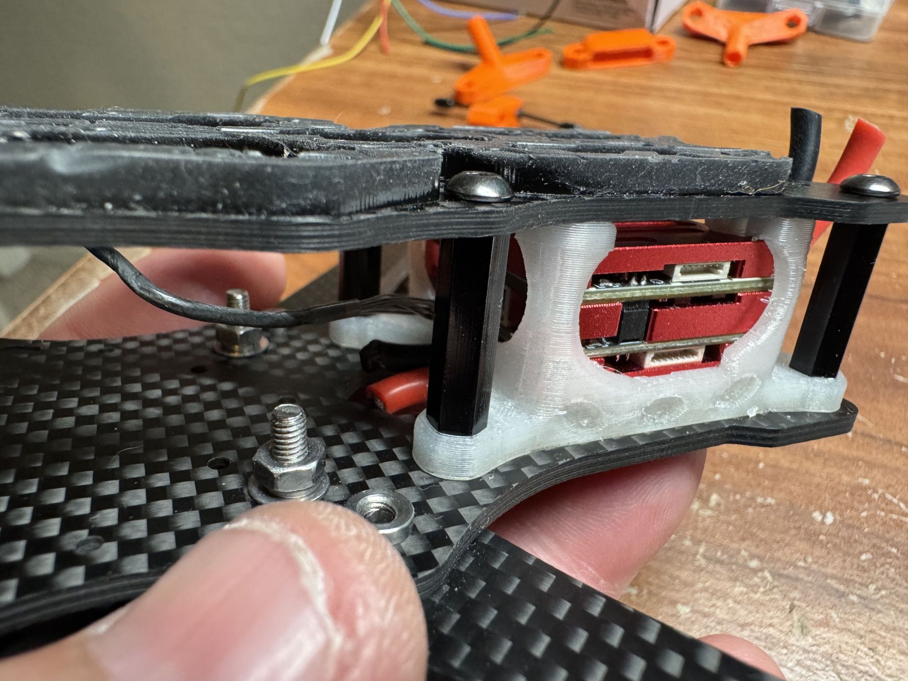
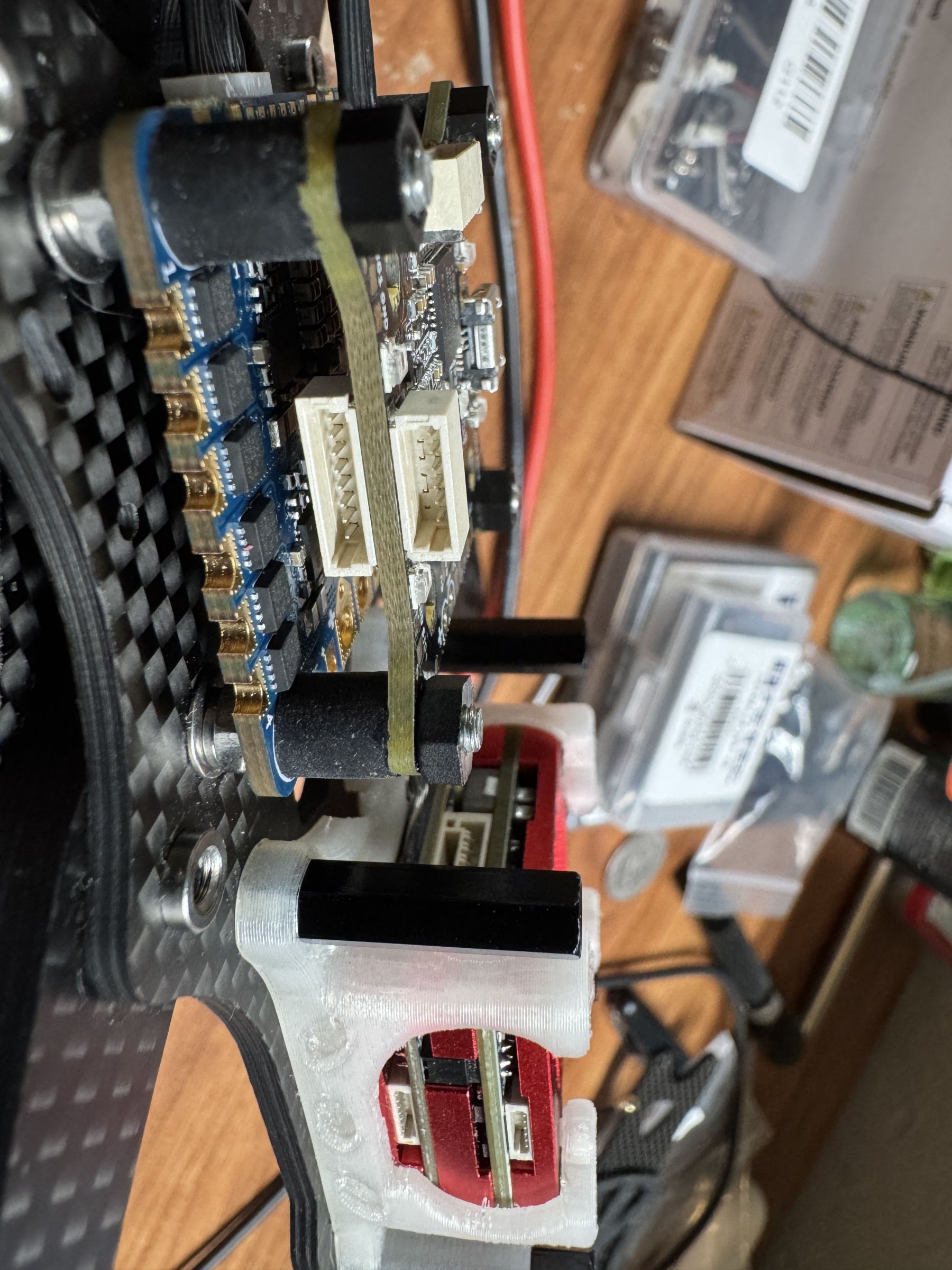
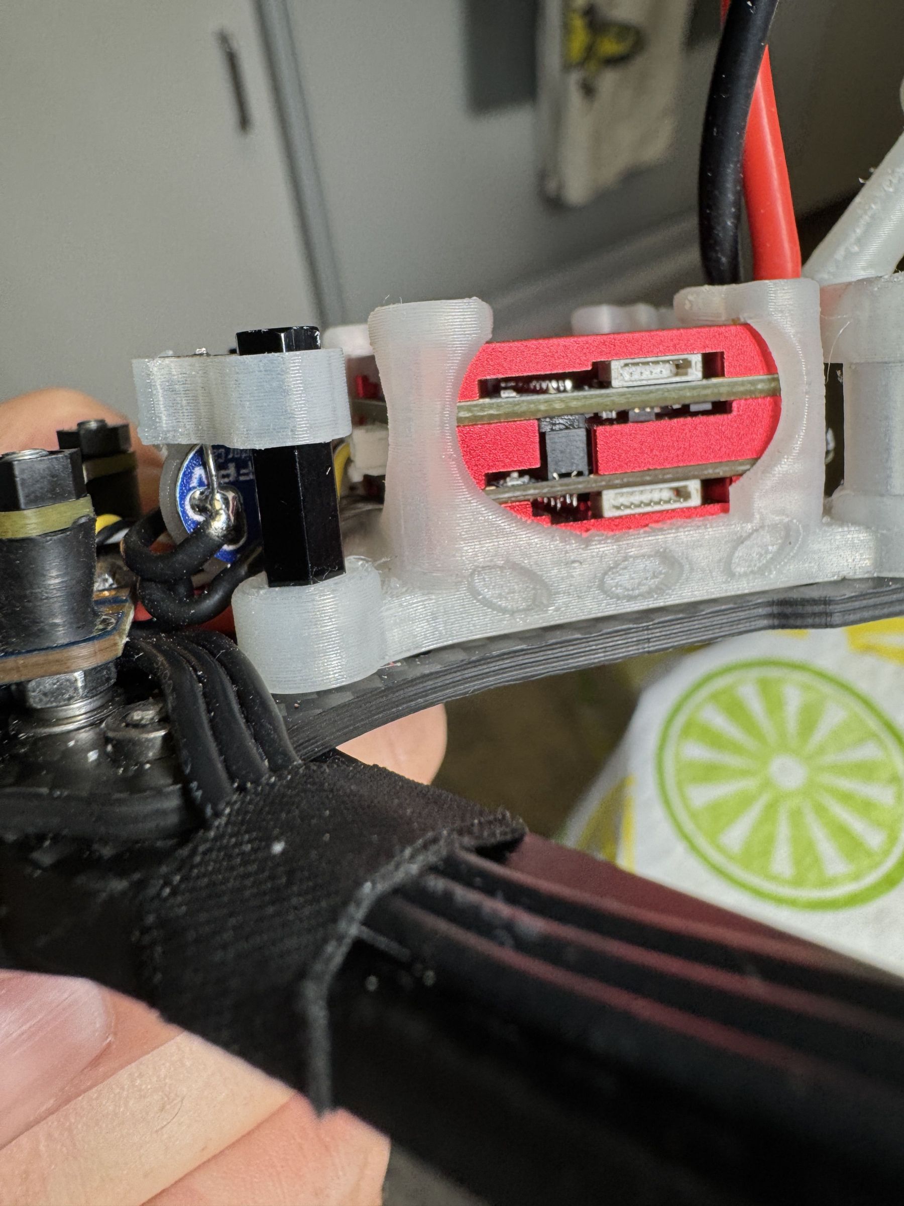
- Chonker VTX must remain electrically isolated from the frame and situated on a TPU couch to provide protection.
- I would need to design parts for this. This is good because it slows me down and causes me to build fewer drones. Makes my wife happy.
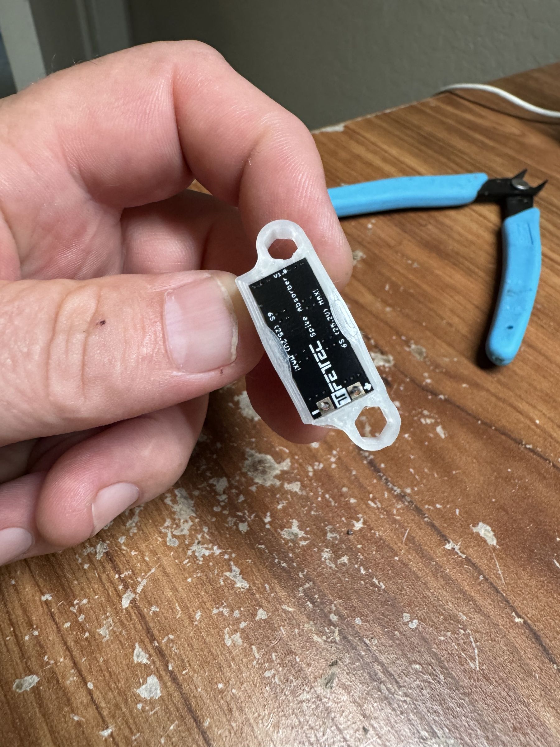
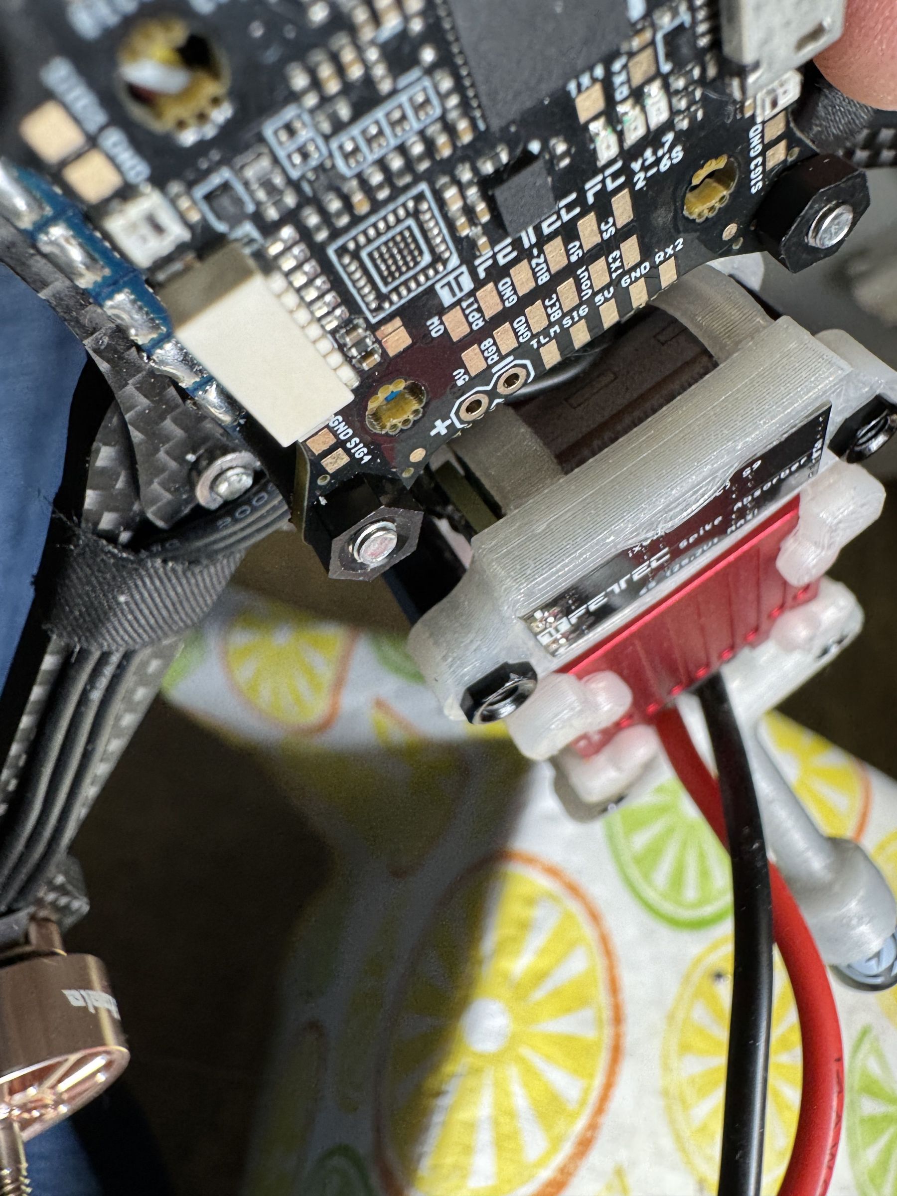
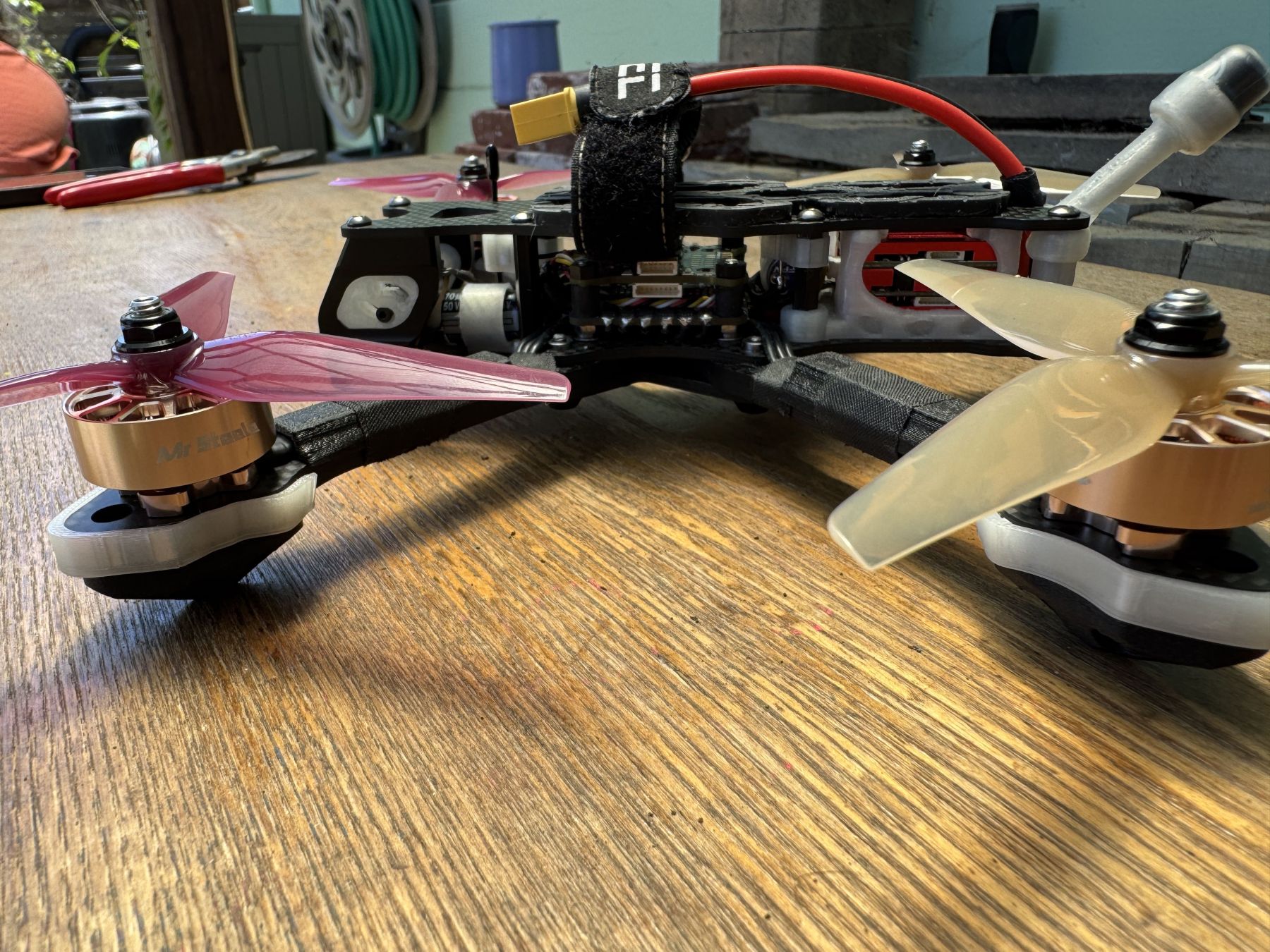
- Custom mounts should also be used for the power-lead capacitor and FETtec Spike Absorber.
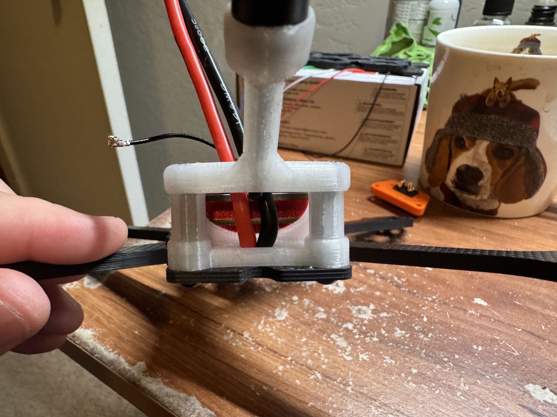
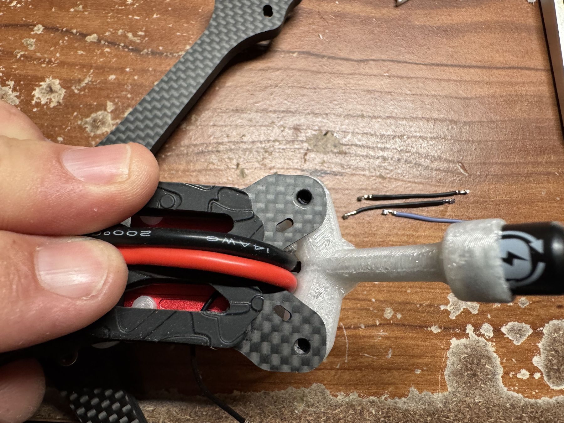
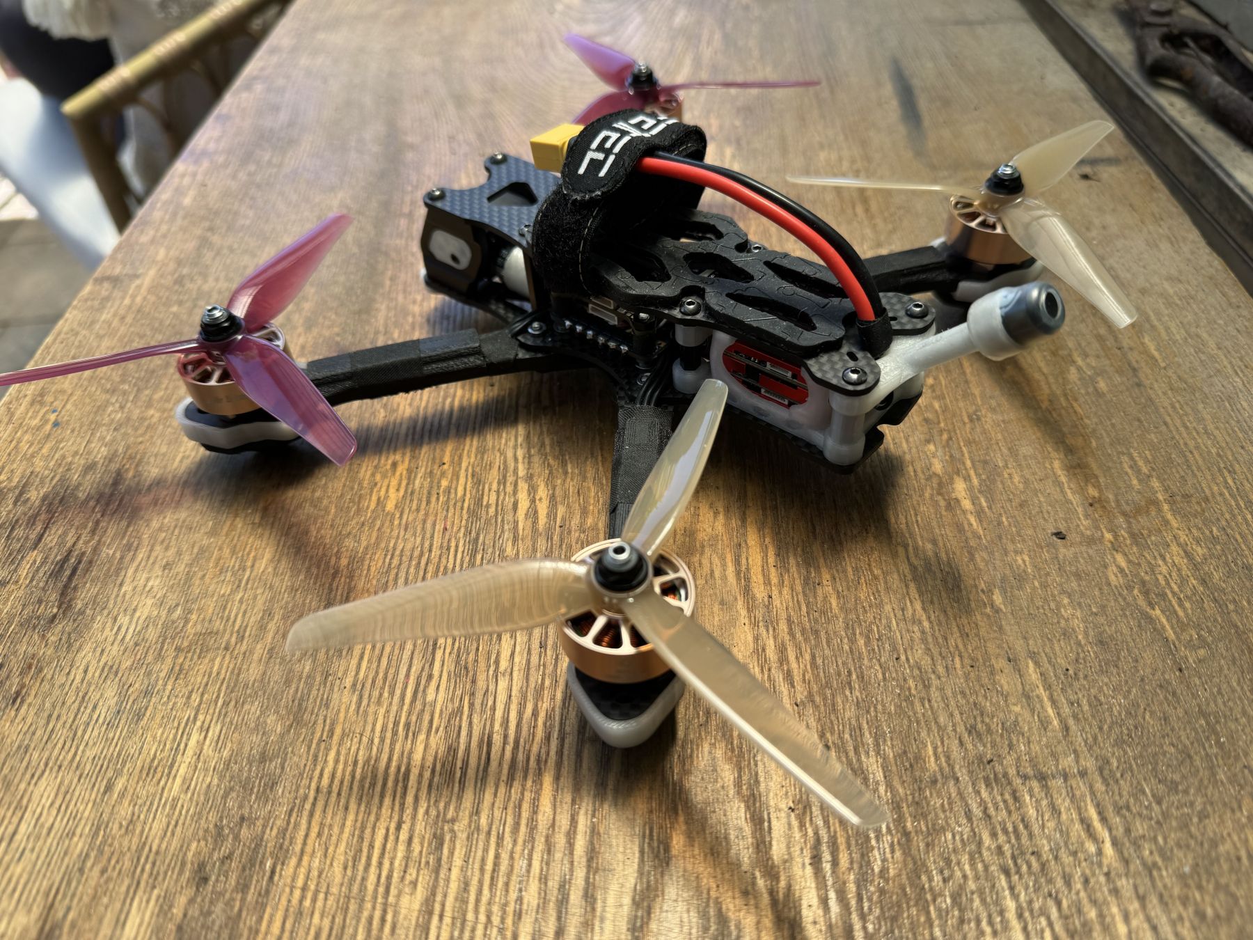
- A custom VTX antenna mount should also be made to match the VTX mount aesthetic and provide protection.
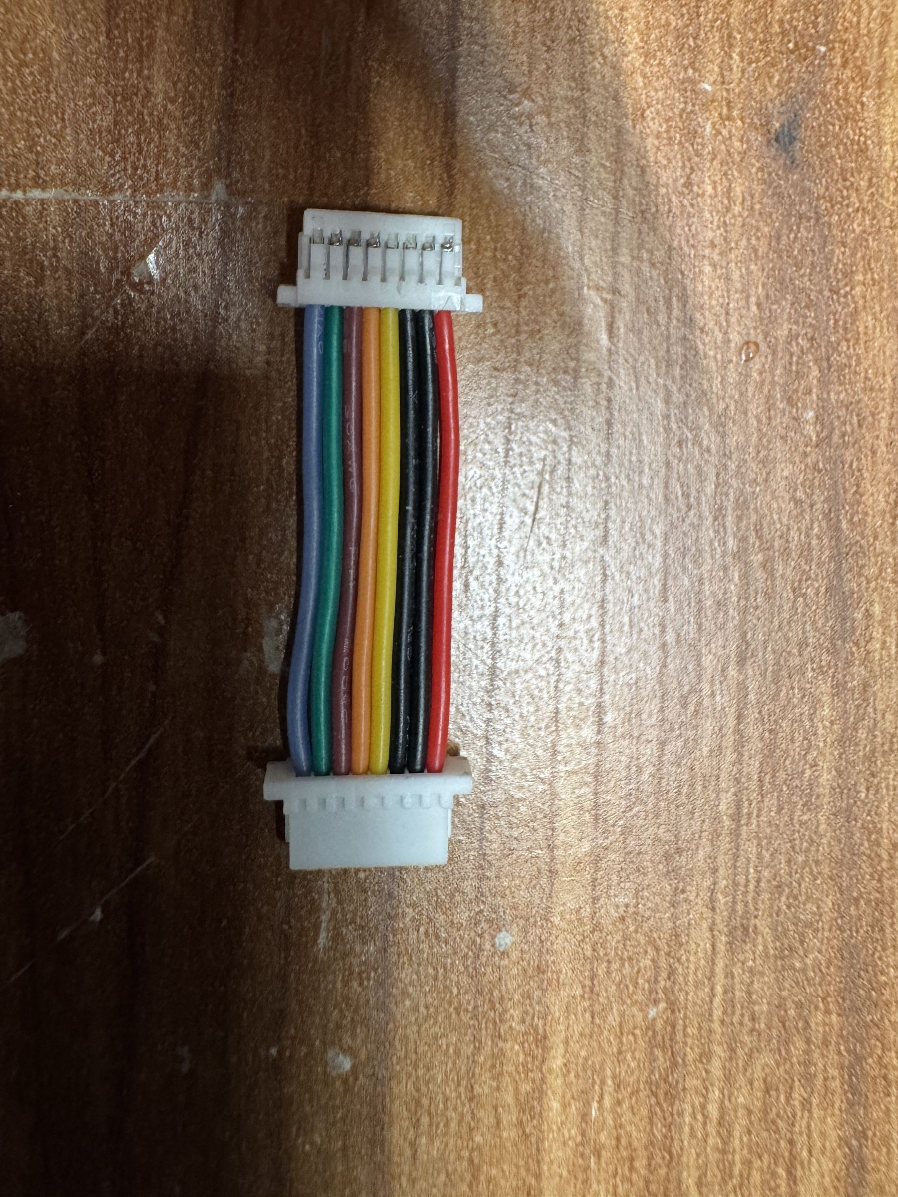
- Wiring should be clean, with custom-crimped harnesses where needed.
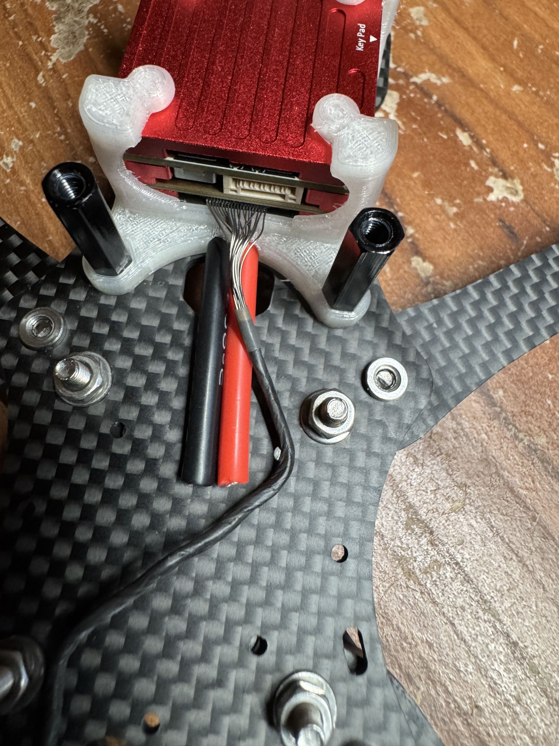
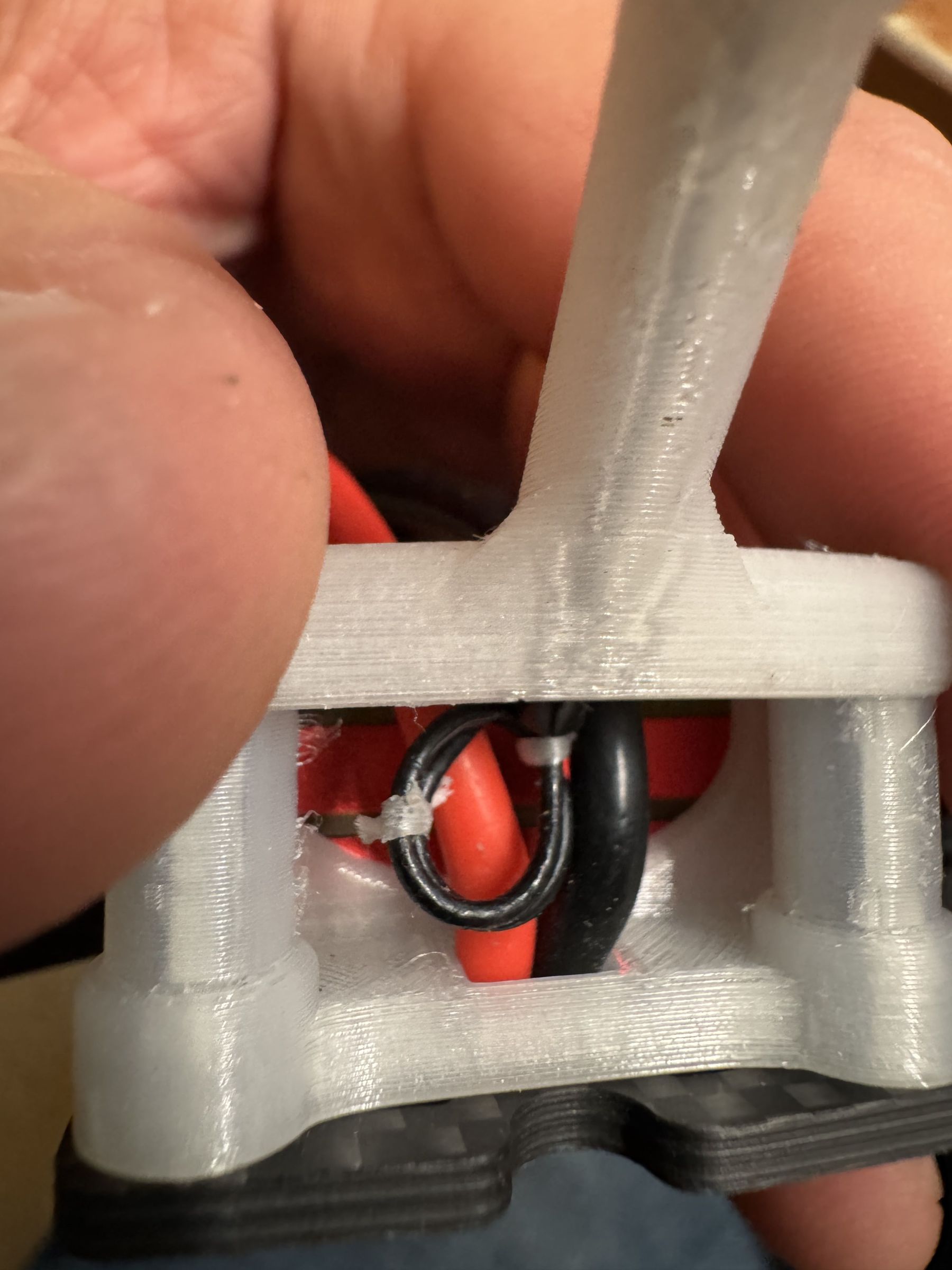
- Power leads should run underneath the VTX.
Aesthetic Requirements
- Custom parts should reflect the Alien aesthetic from ImpulseRC. They should look like they have been abducted by aliens.
- Curves and ovals should be used to reflect a cheesy 1950s sci-fi vibe.
- Parts should speak to each other, requiring remixing and redesign.
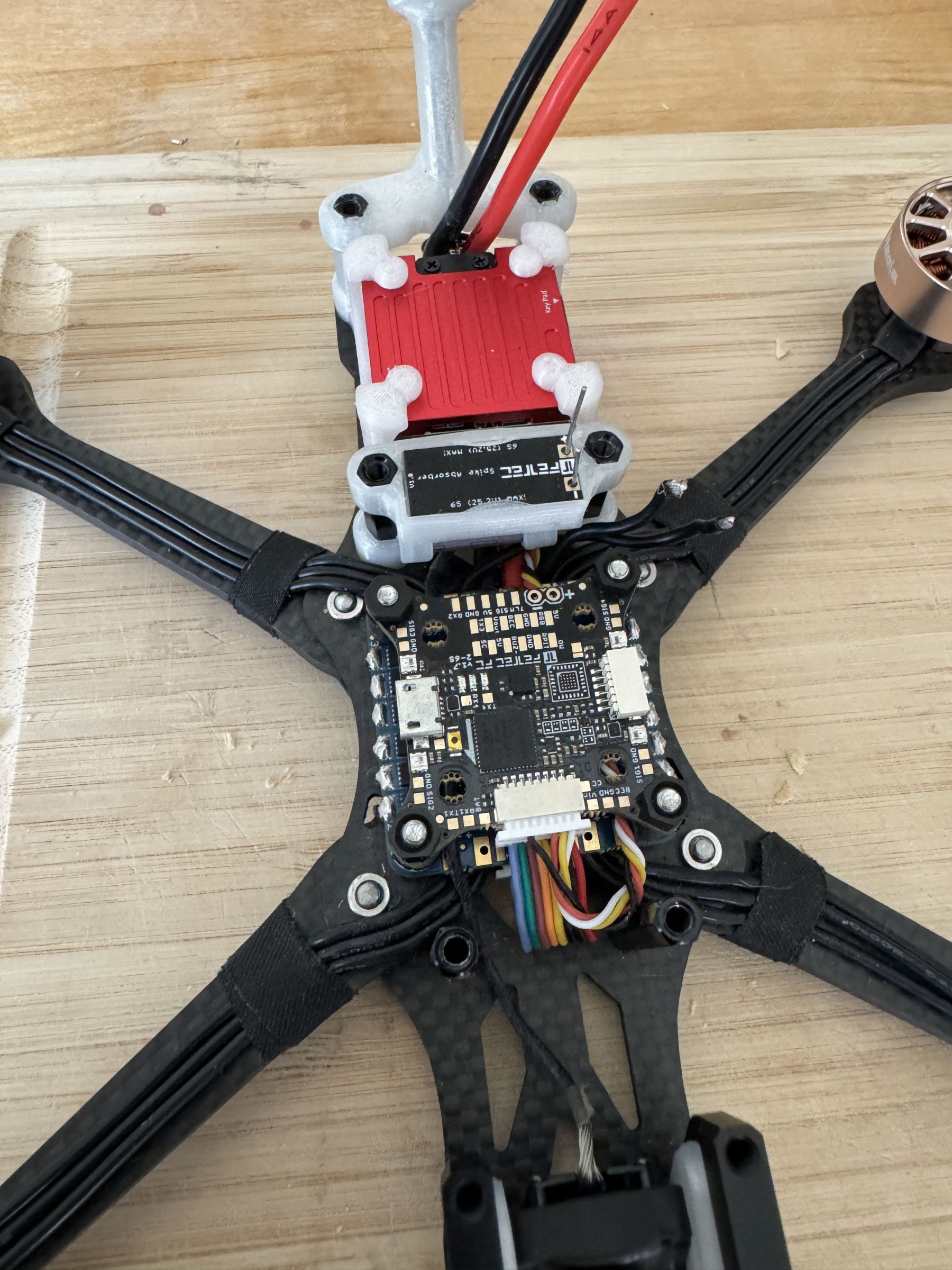
- The FETtec logo on the Spike Absorber should face up. Think if you lift the hood on a Ferrari, it should say Ferrari somewhere.
- Build should accommodate 250 V capacitors the one that came with the ESC as well as a large genuine Panasonic.
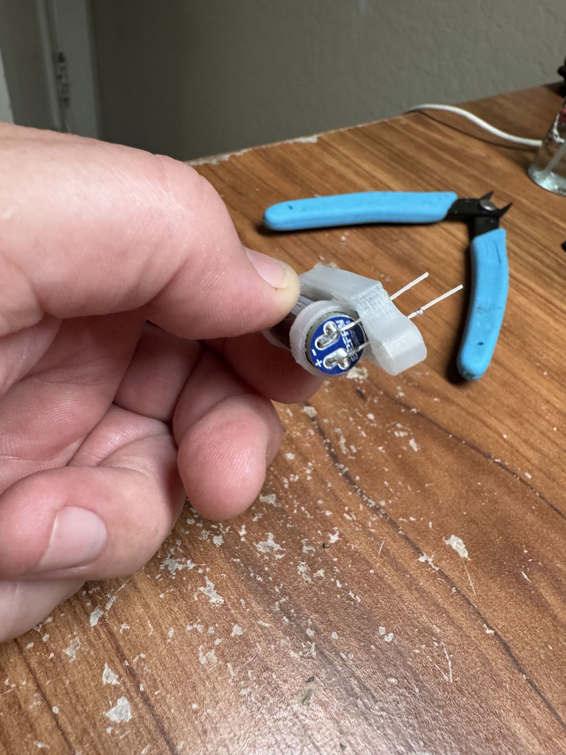
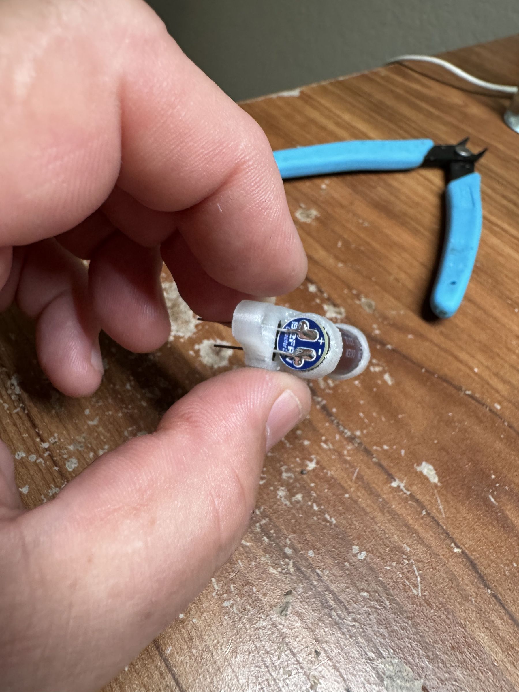
- Capacitors should be situated in TPU mounts and connected with silicone motor-wire trimmings.
- Capacitors should use the B2FPV CappyCaps (Josef is my hero!).
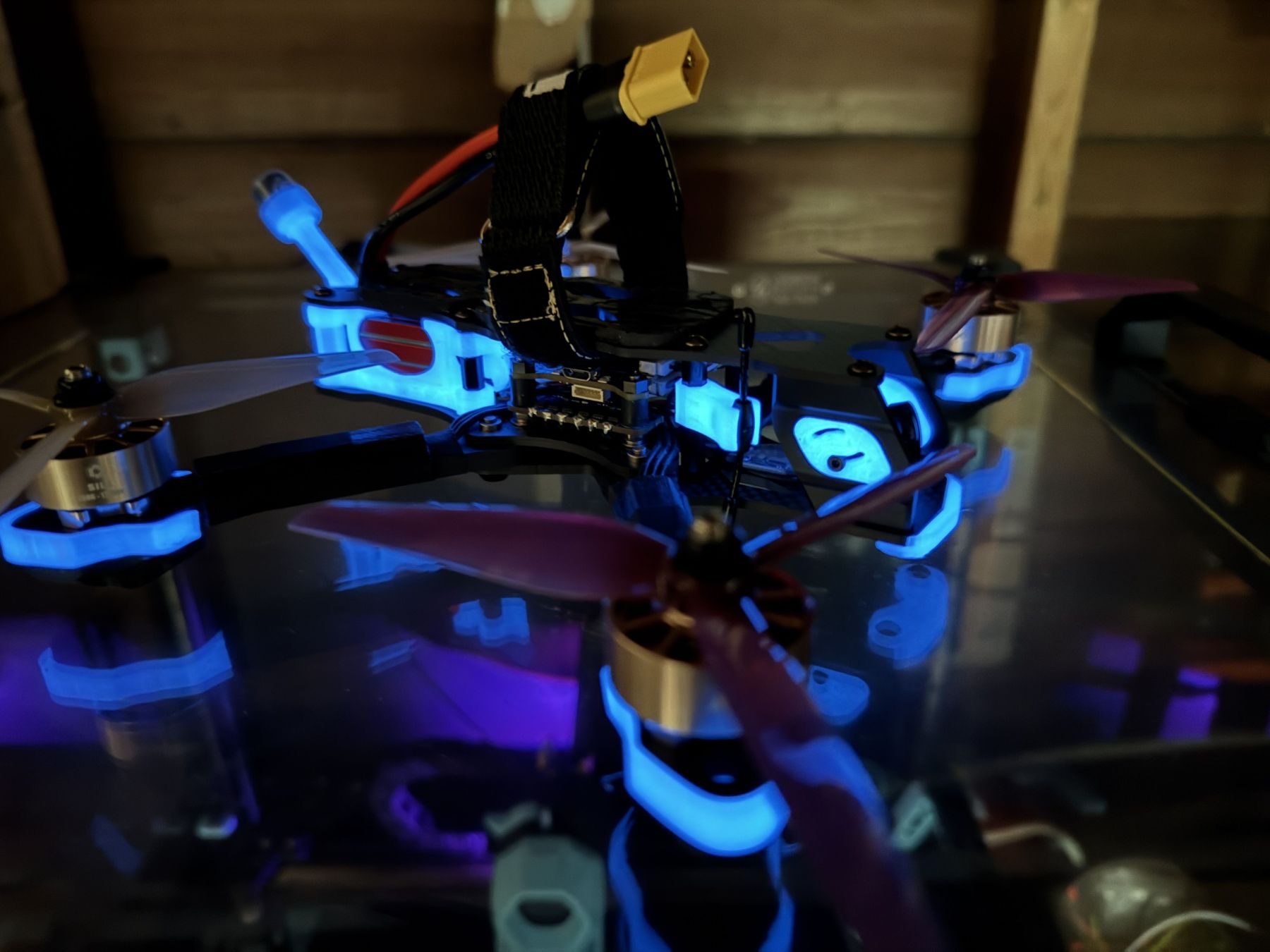
- TPU parts should glow in the dark (because race car).
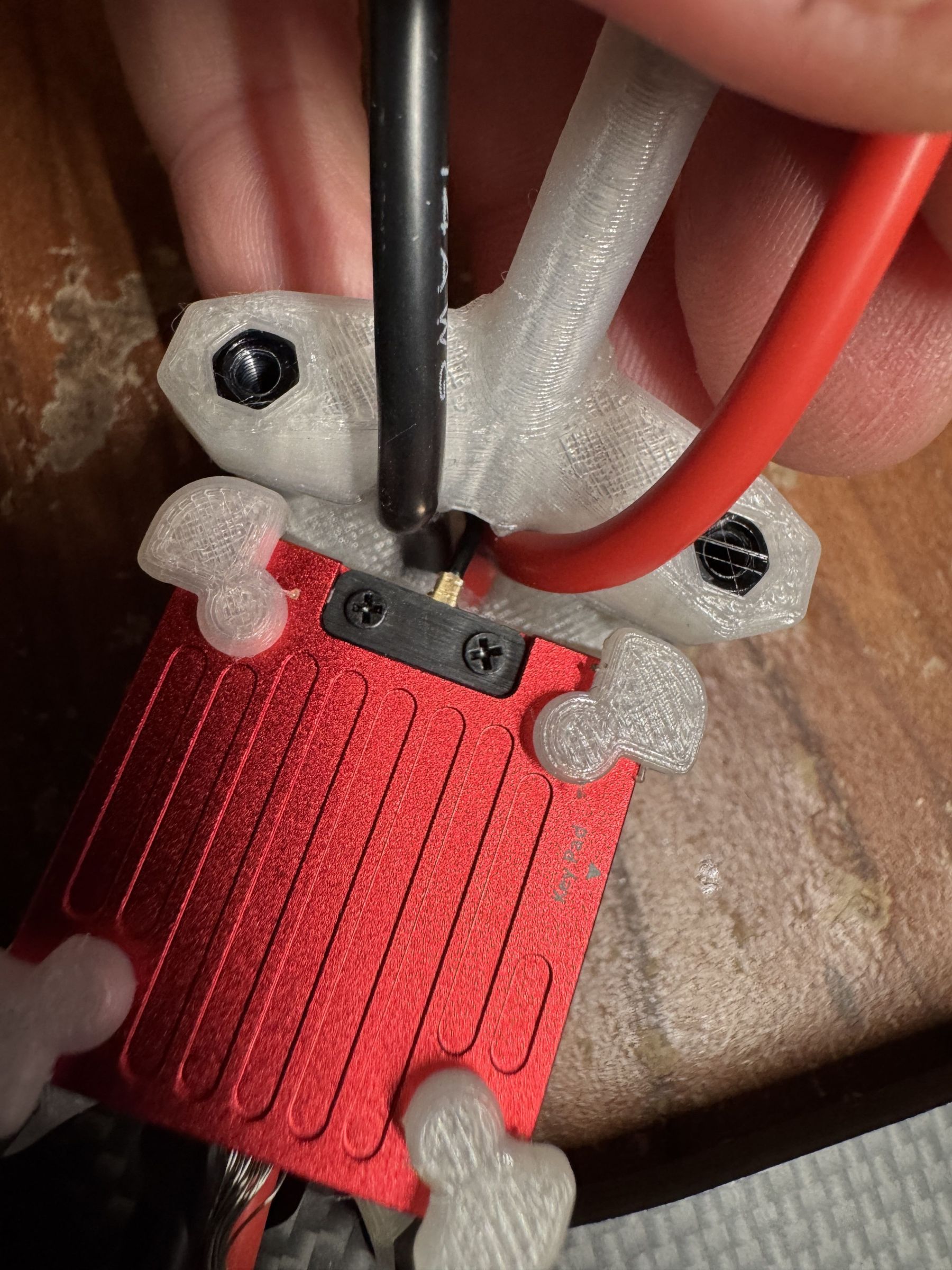
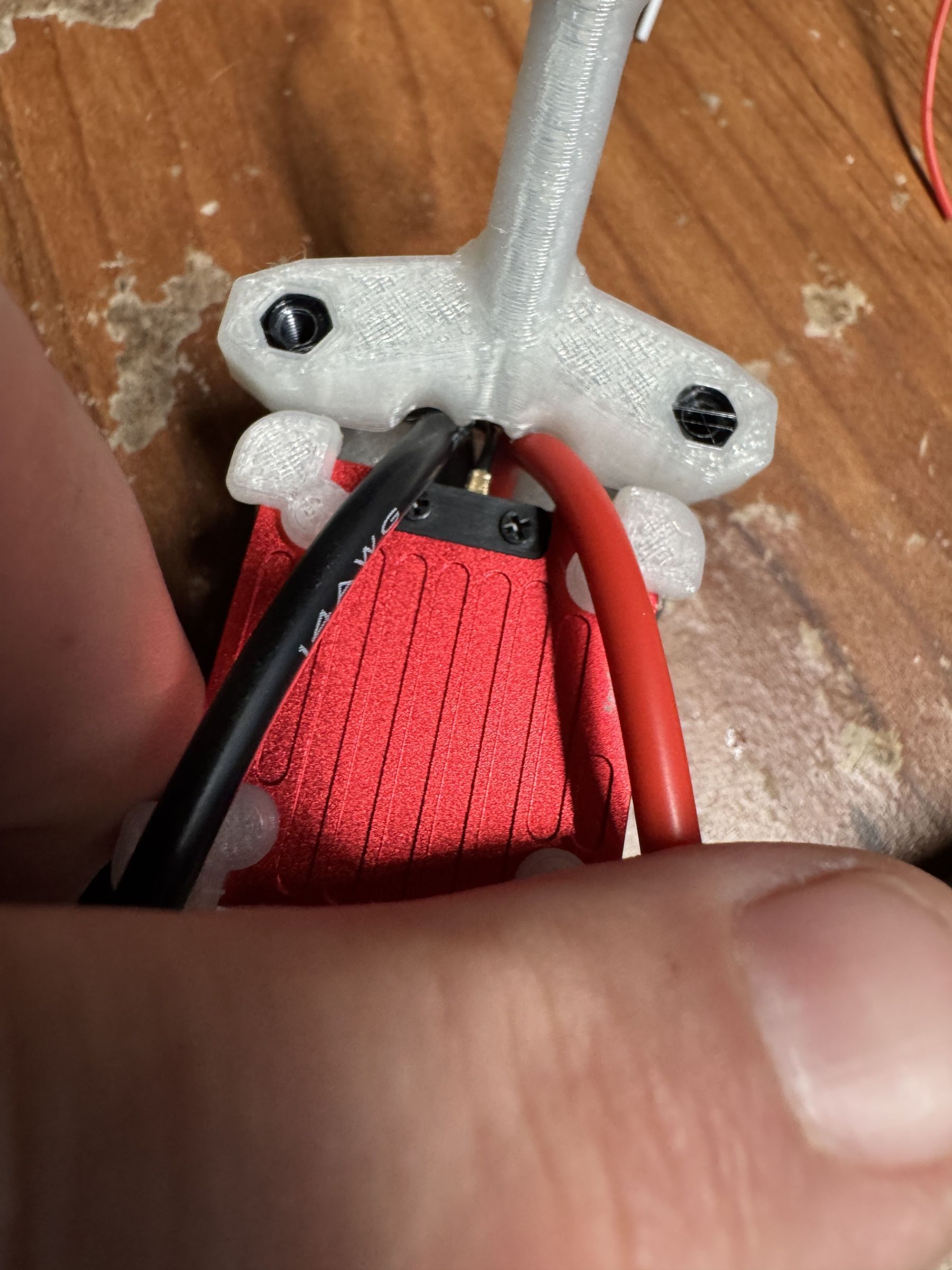
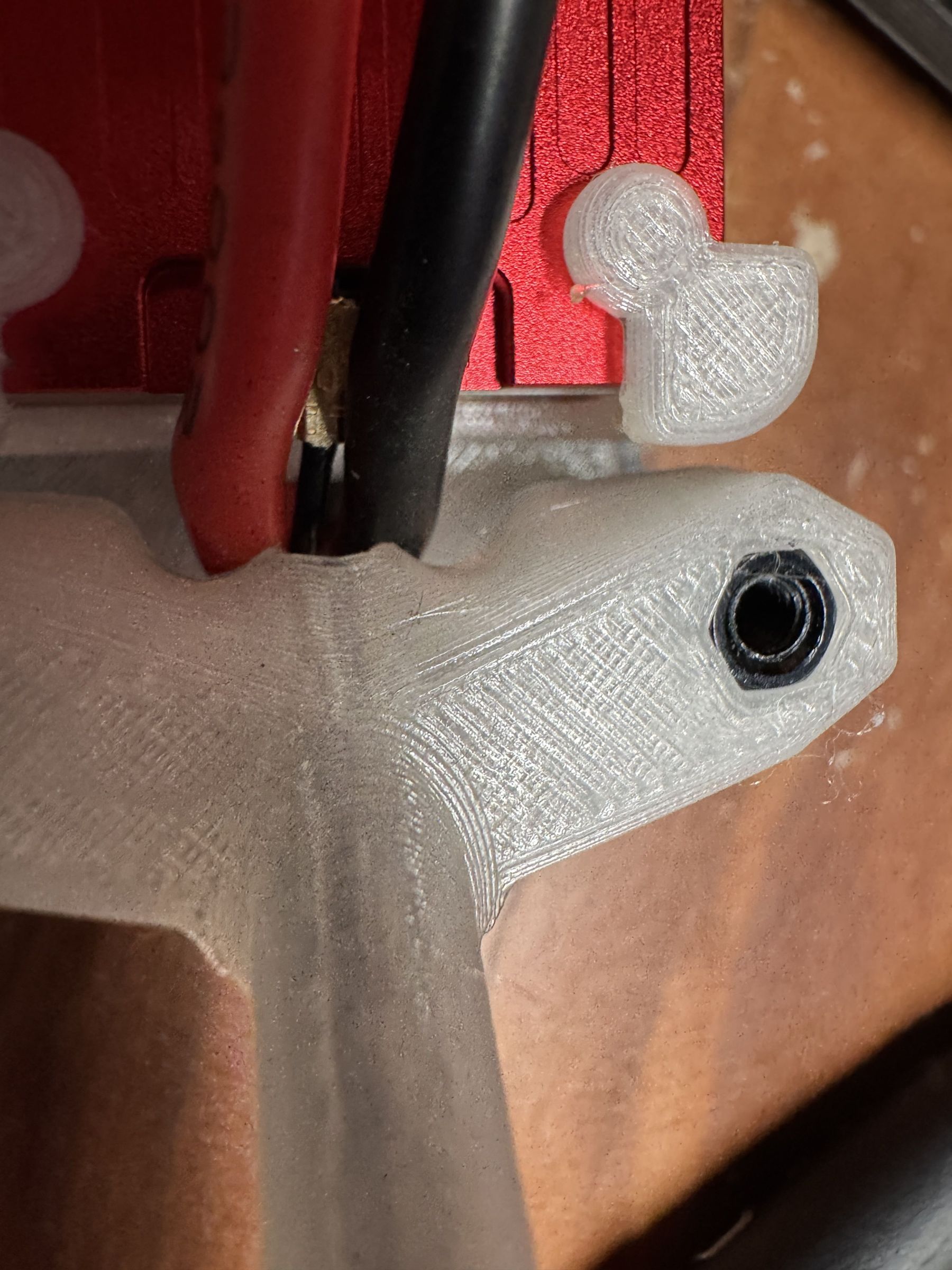
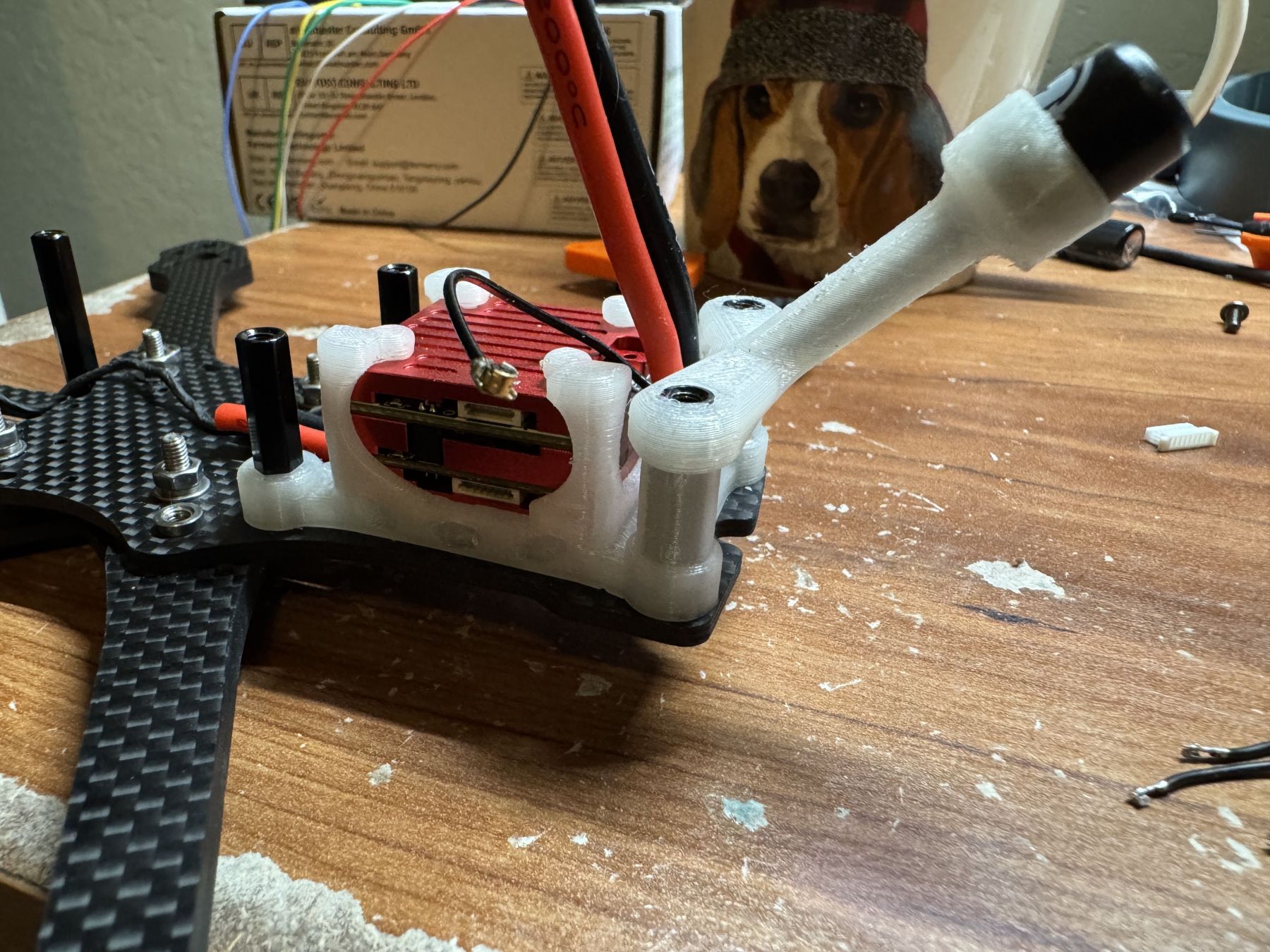
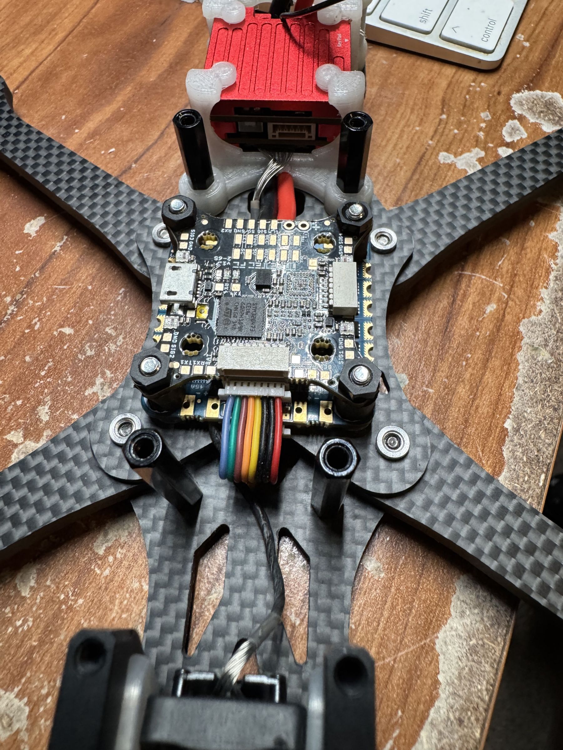
This all started, like most things do, with trying to figure out where stuff goes and how to make room for everything. Its not that the Evo is a tight frame, but the constraints around the chungus VTX and the required Spike Absorber + 50 V cap were pretty limiting. I knew I wanted the power leads to run under the VTX, so designing a mount for that was first on the agenda. It took me forever to come up with something I liked. Originally Id planned to use isolated screws to secure the VTX to the TPU mount, but I thought better of it and decided to squish it into place using some downward force from the top plate. This had the advantage of allowing me to expose all sides of this megachonker aluminum cube to airflow for cooling. With the wires run under it, I thought to myself, Self, is there anything else you can put under that VTX with the space you have? The answer turned out to be no. I could just fit the receiver under there, but it would have caused an RF nightmare at the back end of the quad, so I decided against it based on the advice from my friend ResonantFPV.
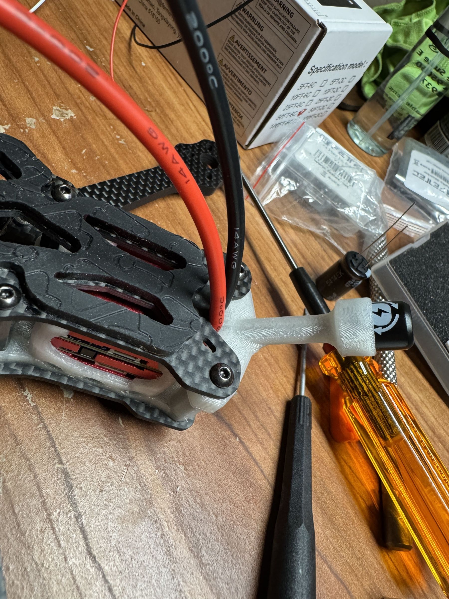
With the VTX mount done and people on FB clamoring for the STL, I could move on to the VTX antenna. This part needed to do two things: provide safe routing of the antenna coax cable and room/guidance for the power leads to keep them from being too squished between it and the top plate. Easy enough with a simple remix of the official Impulse antenna, since they were awesome and provided the STEP file. Just a few cutouts and a lot of fillets.
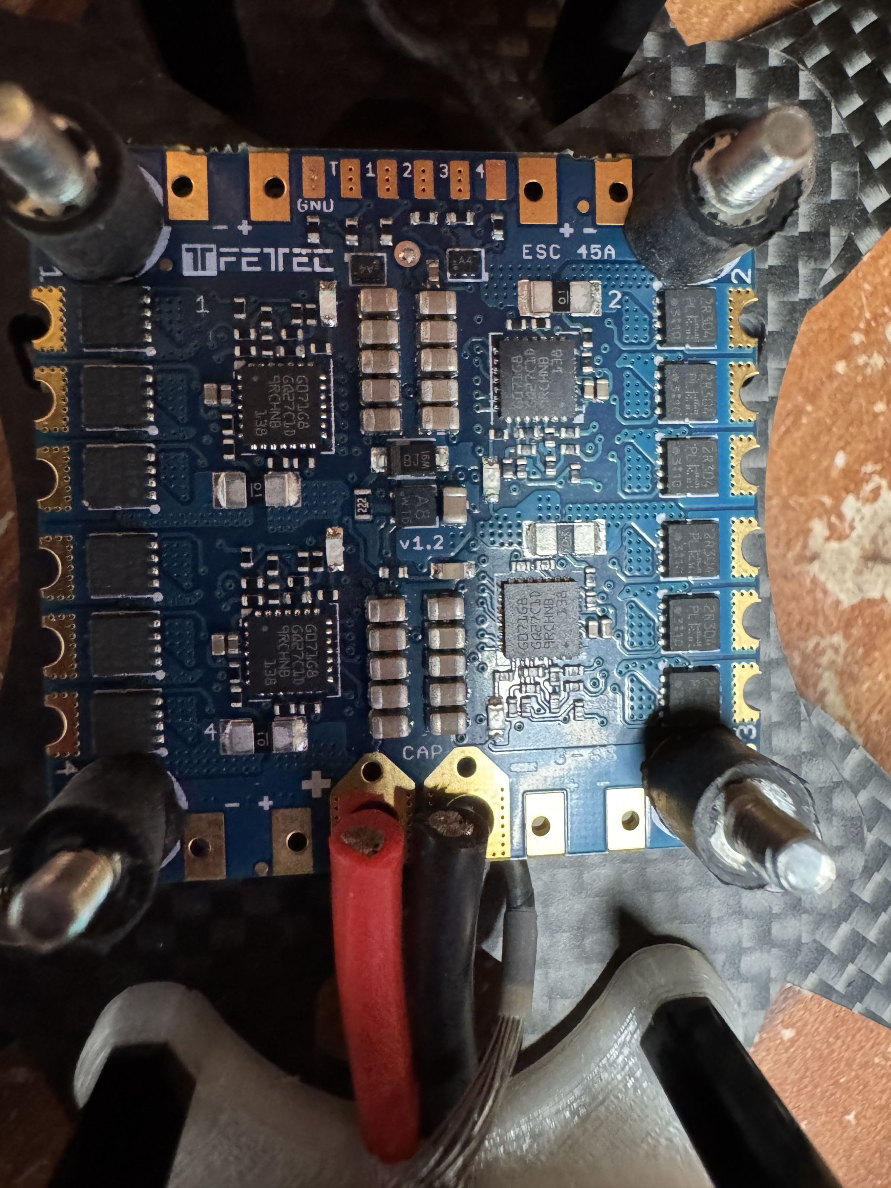
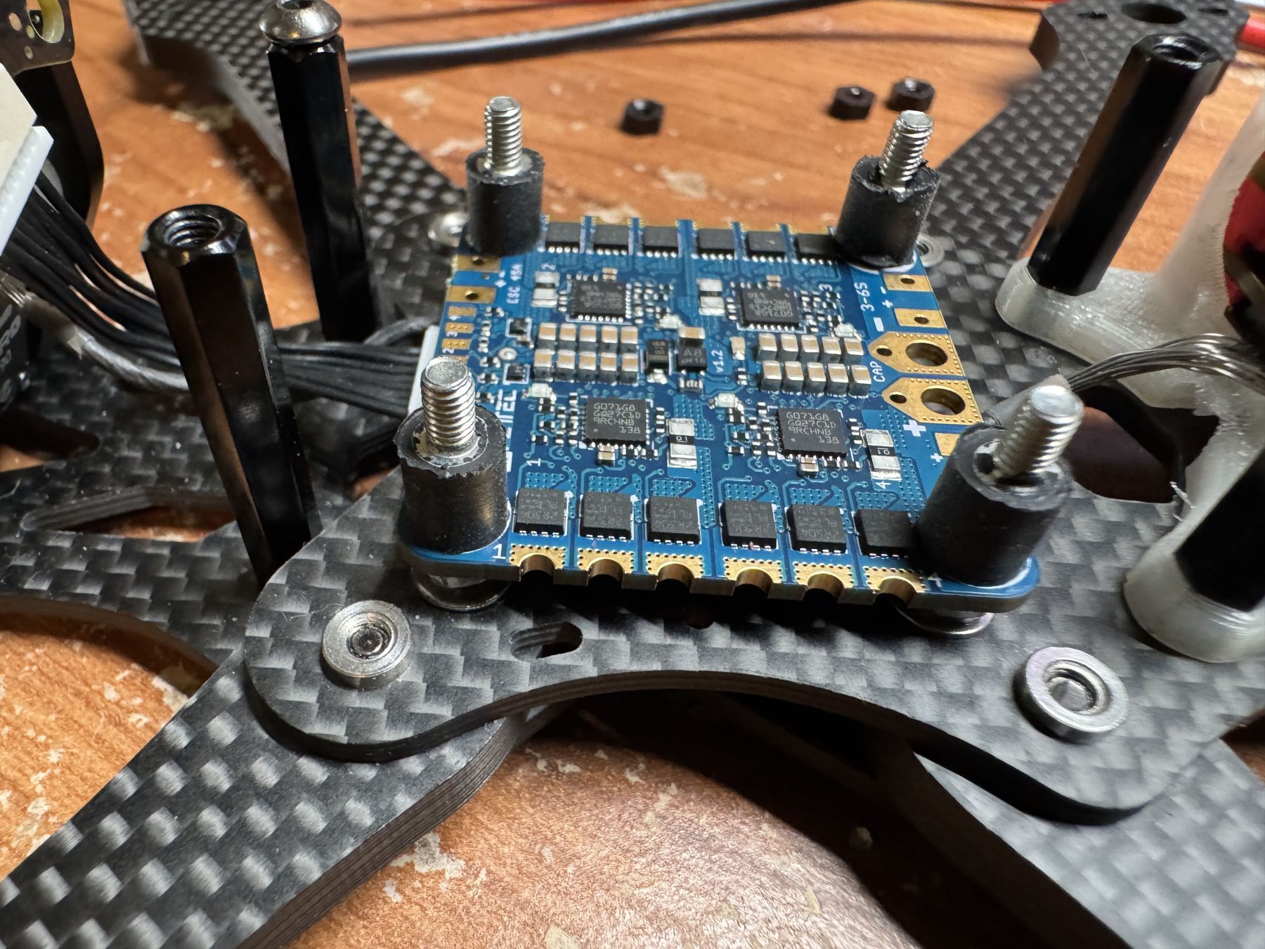
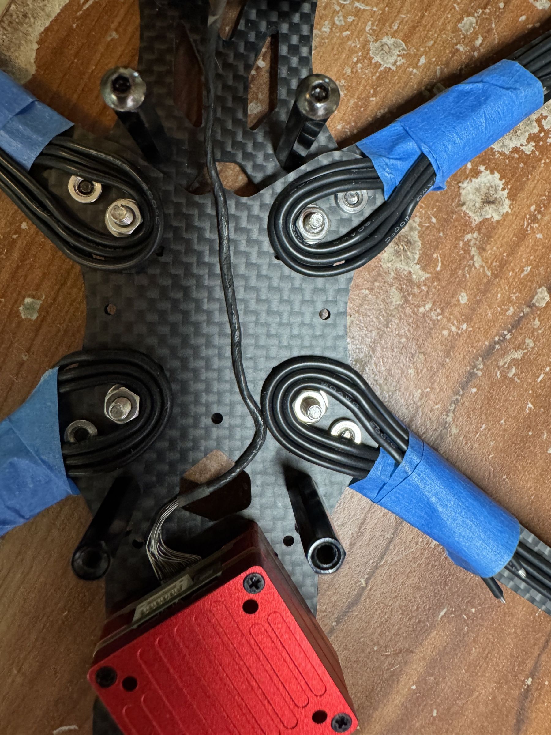
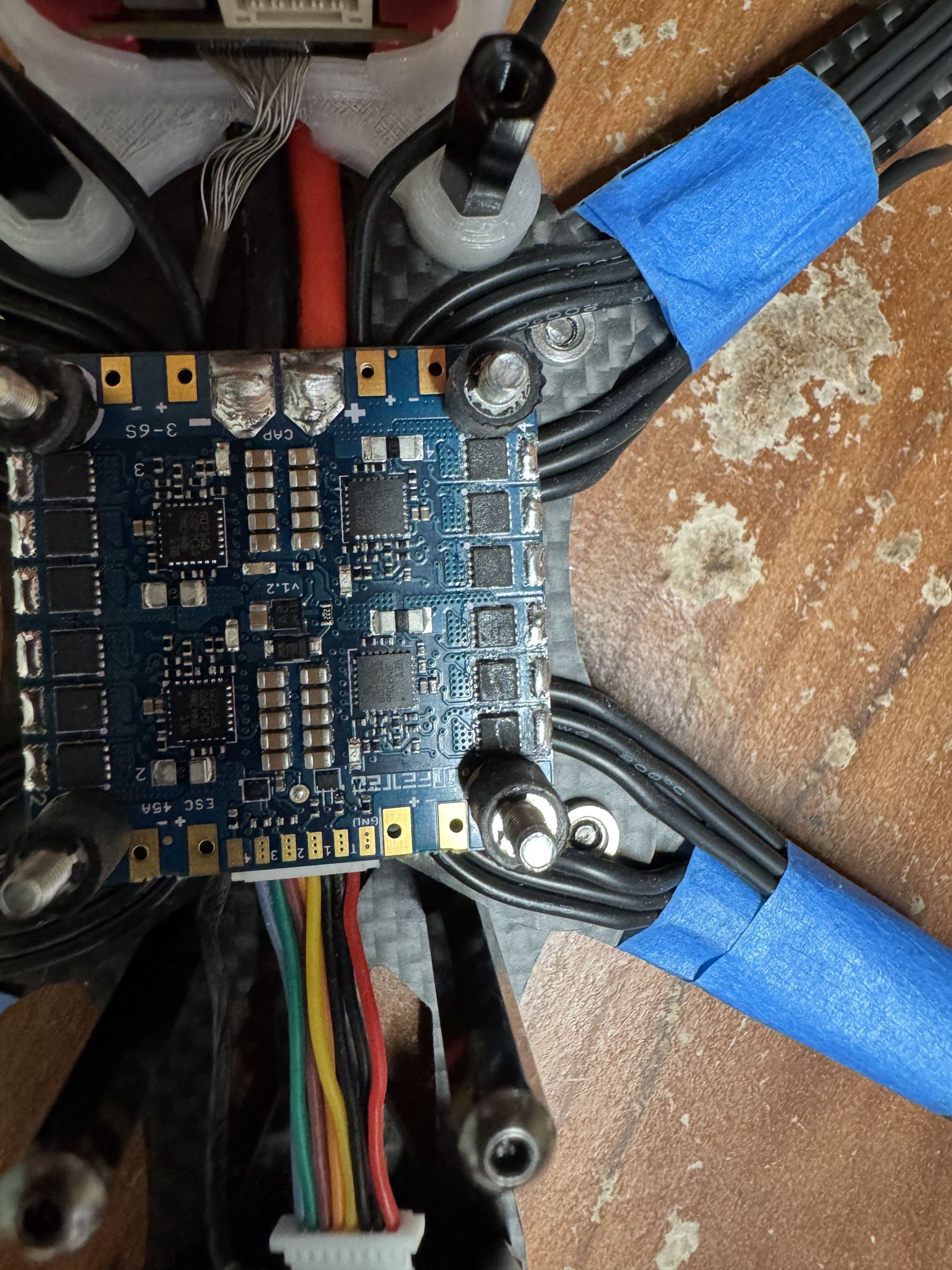
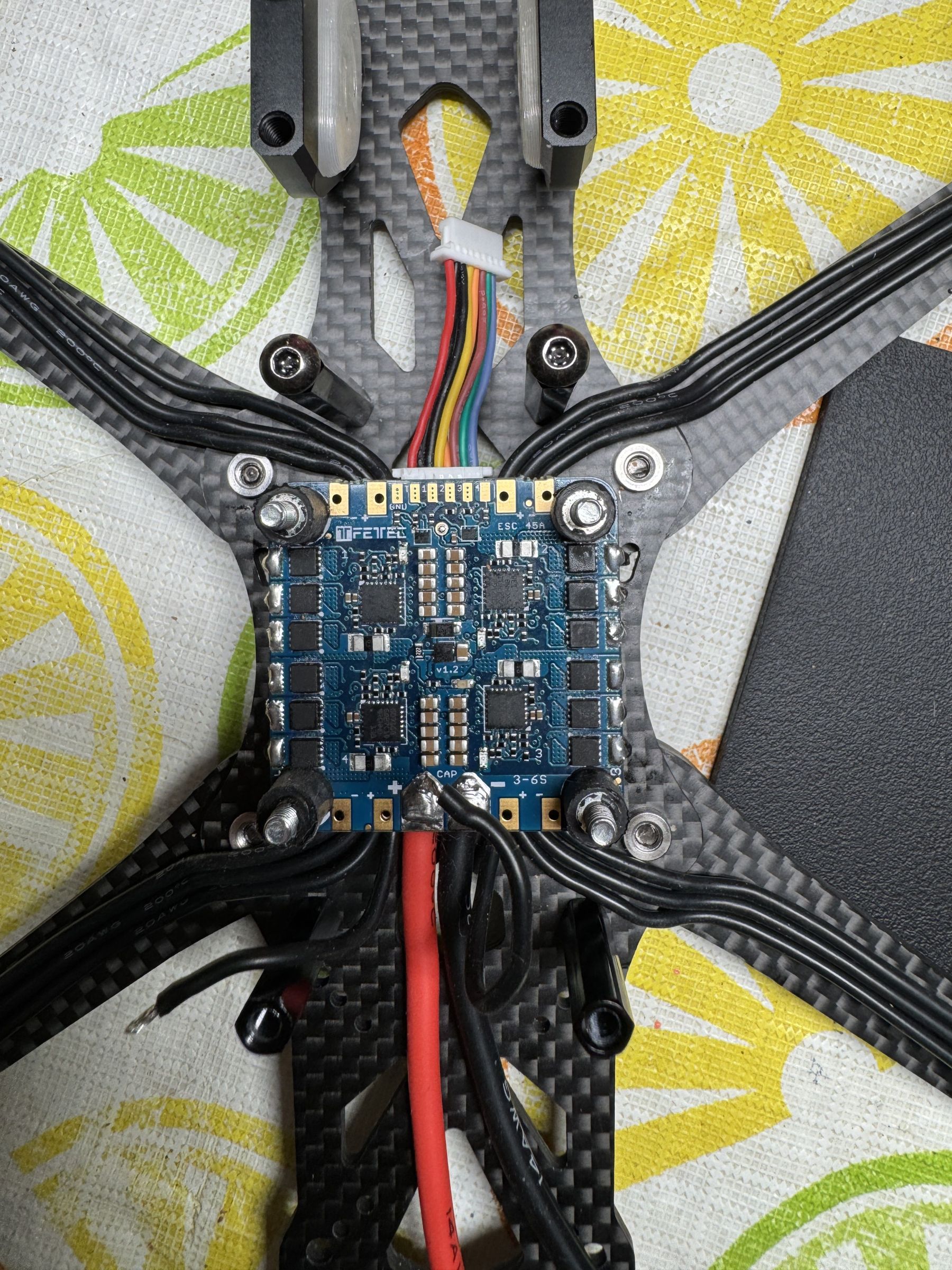
So now were getting somewhere. Time to install the power leads and motors. I thought a lot about this since the ESC has those through-holes. If I just soldered the wires to the top, theyd fill with solder and drip down. If I ran the leads through them from the top, theyd come out at entirely the wrong angle. Soldering them from underneath it was. Stupidly, I decided to use high-lead, low-temp solder for this in an effort to reduce thermal stress on the electronics. This was a mistake because the solder, while creating perfectly serviceable joints, solidifies as a super-ugly, decidedly non-shiny mass that looks a little like the Elephants Foot at Chernobyl. I added flux and reflowed it, but it still solidified matte. The joint, while not aesthetically pleasing, was electrically very good though, so I moved on. Oh, I also included some motor-wire cutoffs in the same joints for the Spike Absorber / cap combo that FETtec requires for 6S.
Next, I spent a few days sticking the capacitor in all the open spaces, seeing where and in which orientation it would fit. Its always nice to situate these vertically if you can, but it wasnt going to happen because its an enormous 50 V cap that needs a PCB with Zener diodes attached to it. Horizontal it was. I kinda quickly realized that this could provide a kinda cool look though, so I started getting excited about it. The TPU part required probably ten iterations and test fits before I got it right, but in the end it resulted in a pretty cool little plaque that reads FETtec when you take the top plate off. I think it looks clean and it hides those matte gray solder terminals, which is nice.
With that done, I could close Fusion and start wiring everything up. I decided to run the motor wires around and under the ESC. I have always thought this method has a nice, clean look to it, but it is a massive PITA. I also understand its not the best for noise management and serviceability. These are things that must be sacrificed for cool looks, and I took the credit I received for moving the receiver up front and cashed it in there. Im mostly happy with the solder joints for the motor wires, although a few could be better. Someone once said, The perfection is in the imperfection.
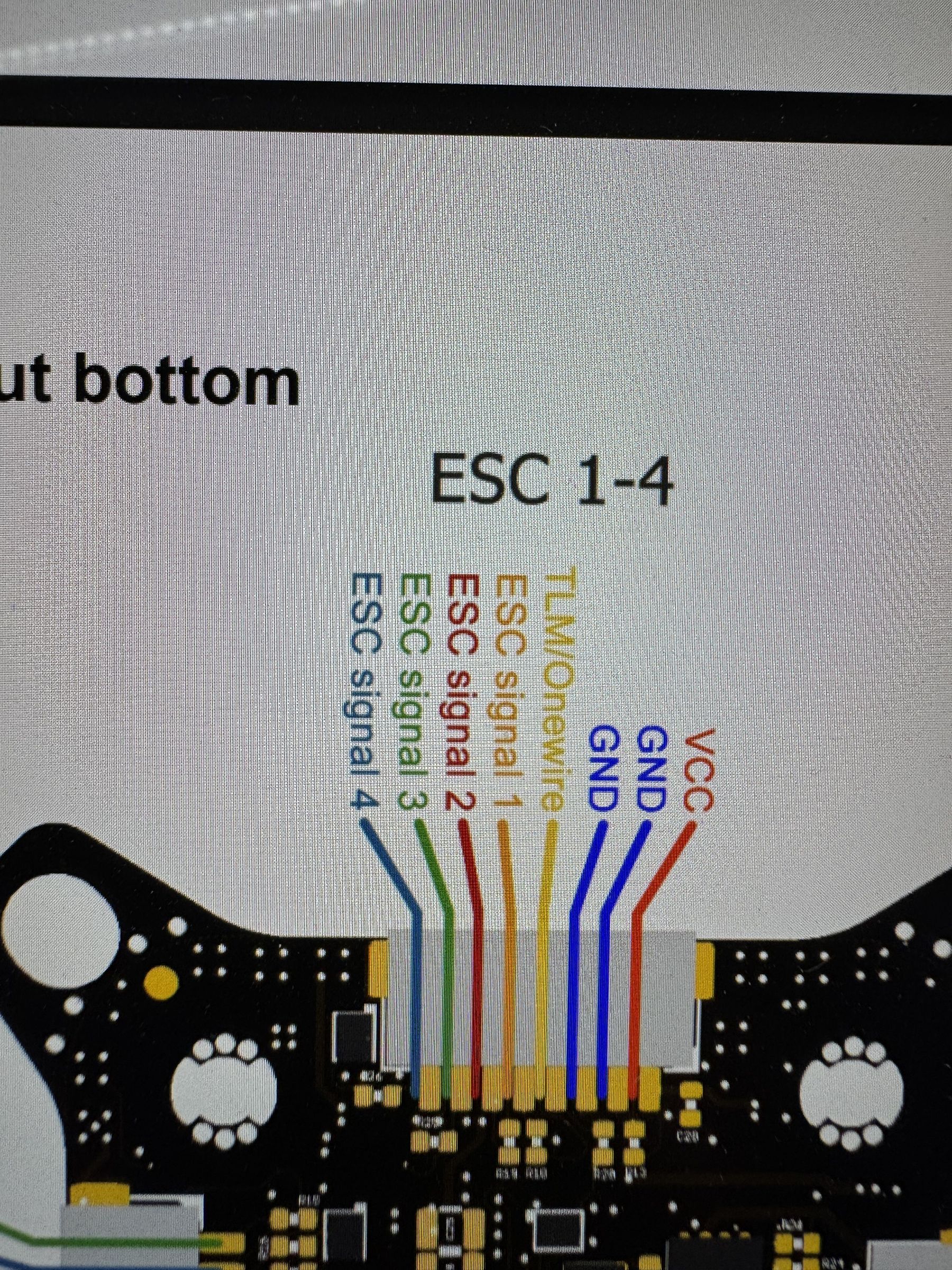
Obviously smoke checks and everything went alright, and I set about trimming wires and getting things into their final home. I got real mad when I realized I could not change the aspect ratio on the stupid camera that comes with the Freestyle V2. I probably should have known this, but I didnt and it made me big mad. Im still mad! Mad enough to give HDZero another $57 for the camera that will support 16:9. Thatll teach em! FETtec Alpha is kinda weird. Not really weird, but kinda weird. Stuff is just not quite where you expect it to be. Its also worth noting that they use a completely different motor numbering orientation than Betaflight. Just something to know, I guess, but it caused some head-scratching as I was trying to work out the ESC orientation. I got the motors spinning the right direction, applied the 5" preset, and took it for the maiden yesterday. Flew great. I didnt even do a test hover. I just went to a big, soft, grassy field and let her rip on flight #1. Really happy with how it performs right off the preset.
It sucks we cant get real versions of this frame anymore. Hopefully the IP holders will open-source the design so we can keep the arms and plates flowing from companies that are not the Chinese counterfeiters who probably put Impulse out of business to begin with.
I hope you like my build. You can download my STL and STEP files from my GrabCad account.
Source: RotorBuilds.comGalerija